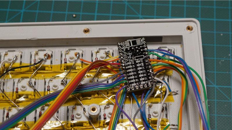
It’s finally time to get our hands dirty.
For the sake of this tutorial I designed and 3D printed a small case that will serve as the base structure for my handwired keyboard. It doesn’t matter what case you use anyway, the procedure is the same from a 40% to a full sized keyboard; you are only limited by the number of inputs on your main controller but up until a tenkeyless you should be good with pretty much anything (teensy, arduino, promicro, …).
If you prefer visual gratification, here below you’ll find a video tutorial but this article will also cover some theory about the matrix so I guess it’s worth a read.
What you need for this project
Let’s see how our Bill Of Materials looks like.
- The switch plate.
- Enough switches to cover your keyboard (duh).
- 1N4148 through hole diodes, one for each switch. They are extremely common and general purpose, you can find them on Mouser, Digikey, Ebay or even Amazon.
- Solder wire, I usually go for 0.6/0.8mm gauge.
- Electric wire, single strand, to connect rows and columns. I’m using 0.6mm gauge internal/1.0mm external but anything works, just don’t go insanely small. Technically you could also use enamel wire but I figure it’s easier with standard wire.
- Rainbow flat ribbon cable. It will be used to connect rows and columns to the controller. It doesn’t need to be “rainbow”, any wire will work, but it helps tracing what goes where.
- Any kind of insulation tape or means to insulate the rows from the columns (vinyl sheet, electrical tape, heat tape, …) or actually nothing if you are using enamel wire. Keep reading, everything will be cleared.
- The main controller, I’m using a Teensy 3.x
Of course you also need a soldering iron, also a glue gun could be helpful (but not strictly needed).
A keyboard matrix
While a complete understanding of what is going on electrically is not needed, I believe it is worth spending a few moments talking about how a matrix works.
Why do we need a matrix of switches in the first place?
We could connect each switch directly to a pin on the controller and so having a 1:1 switch to input ratio. That would probably be ideal in terms of performance and circuit simplicity but a keyboard is often composed by over a hundred switches. While you could probably find a big enough MCU to handle that or even connect multiple MCUs together, it’s definitely not practical or optimized.
So we put the switches in a XY grid and connect only the rows and columns to the controller. Like in a battleship game to identify which switch has been pressed you need to check both X and Y coordinates. A 10 by 10 grid would need 100 inputs if switches were connected directly to the MCU, but only 20 using a matrix.
To have our matrix working we also need resistors and diodes.
We live in an analog world but our controller expects 0 or 1 to tell if a key is pressed. To do so we program the firmware to read the state of the inputs at set intervals. If the value is HIGH it mean that the pin is “excited” by current (it is pulled to VCC, usually 5v or 3.3v); if the value is LOW we pressed the key and we pulled to ground. This is easy to say but practically the MCU doesn’t know how much low is really LOW or how much high is really HIGH. To solve the conundrum we use a pull-up resistor that helps to disambiguate this floating state.
With a pull-up resistor a small amount of current will flow between the power source and the input pin on the MCU exciting it into a HIGH state. As soon as you press the button the circuit is closed, current will flow to ground passing to the resistor (preventing a short) and the value will be correctly read as LOW (not excited, give me my current back!).
Why are there no resistors in our BOM if they are so important? Well, fortunately pull-ups are so common that most MCUs come with integrated resistors for each pin. So you read the past few paragraphs for nothing but it’s nice to know what’s going on anyway.
The situation about diodes is a bit more complicated. Without delving into too many details this is what happens.
To check what key is pressed we send a signal to each column sequentially, one at the time, from the first to the last. At any given moment only one column is active, all the others are dormant. What happens if I press a key that is on a column that is not scanned in that moment?! Even a relatively slow MCU can scan a matrix hundreds (if not thousands) of times every second while the fastest typist can hardly press more than 15-ish keys per seconds. So, lucky us, that wouldn’t be an issue.
Now that the controller is listening to one column all left to do is checking if any of the switch on that column is pressed. The problem is that if we start pressing more keys at the same time we could create some current loops because current loves to wonder around. That could lead to false positives or even destroy the controller.
To save the day comes the diode. It is a very simple component that basically forces current to go only in one direction and prevents the dreaded loop. We effectively create a forced path for the current that cannot go where it is not supposed to.
Old keyboards or even modern cheap ones come with the bare minimum number of diodes required not to fry the controller, but they often introduce ghosting, jamming or they purposely limit the number of keys you can press at the same time. Since we are building our own custom keyboard, we want things to be perfect and we are going to add one diode for each switch. That makes our matrix rock solid and grants the notorious NKRO.
A quick digression. 1-diode-per-switch grants hardware NKRO but it does not make your keyboard NKRO. That has to be implemented in the firmware. So while it is true that this design is for N-Key-Roll-Over, if not properly supported by the firmware, you will be still very likely limited to 6-KRO
Soldering time
Take your switch plate and position all the switches in it. We are placing the switches upside down, with the LED slot on the bottom (it is usually on top). When you turn over the plate the pins should be all on top.
Since there’s no PCB holding the switches you may want to add a drop of hot glue for each switch so they won’t snap off when removing keycaps.
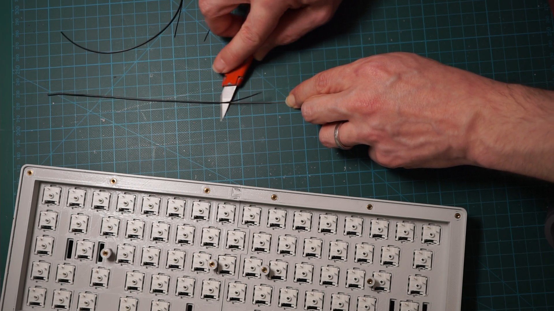
Next we cut 5 wires to the length of the inside of the keyboard and peel them off of the plastic insulation. You should end up with 5 pieces of naked wire that we will use to connect all switches in each row. To make the solder stick to the wire you can scratch it a little with a hobby knife or some rough sand paper.
Heat up the soldering iron to about 290°C and put a little of solder on the left pin of each switch. That’s where we are going to put the diodes, having a spot of solder on the pin already will make soldering the diode much easier.
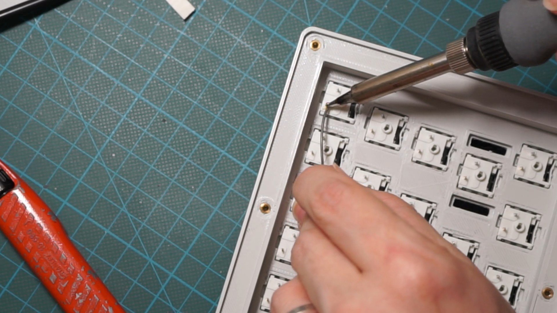
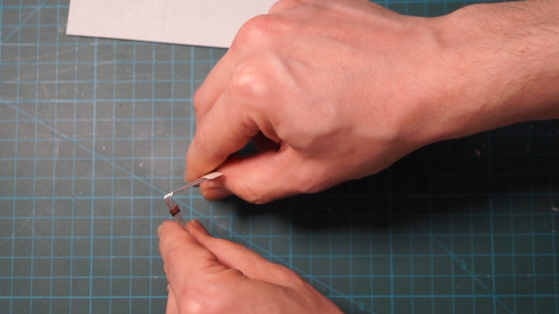
Take 6-8 diodes at the time and bend the anode pin at 90 degrees as shown in the picture below. Diodes allow current to flow only in one direction, from the anode to the cathode. It is very important to orient the diode correctly because they only work in one orientation. It is also the most common mistake in hand-wired keyboards.
Generally the cathode side is identified by a small black band on the 1N4148. So this time be sure to bend the pin on other end.
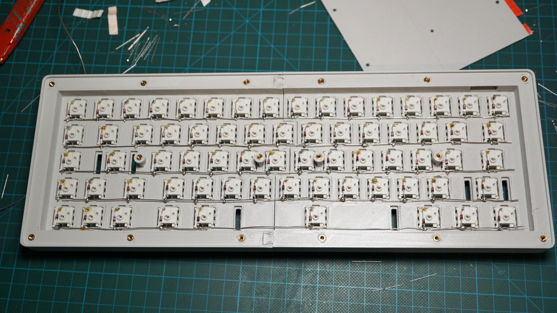
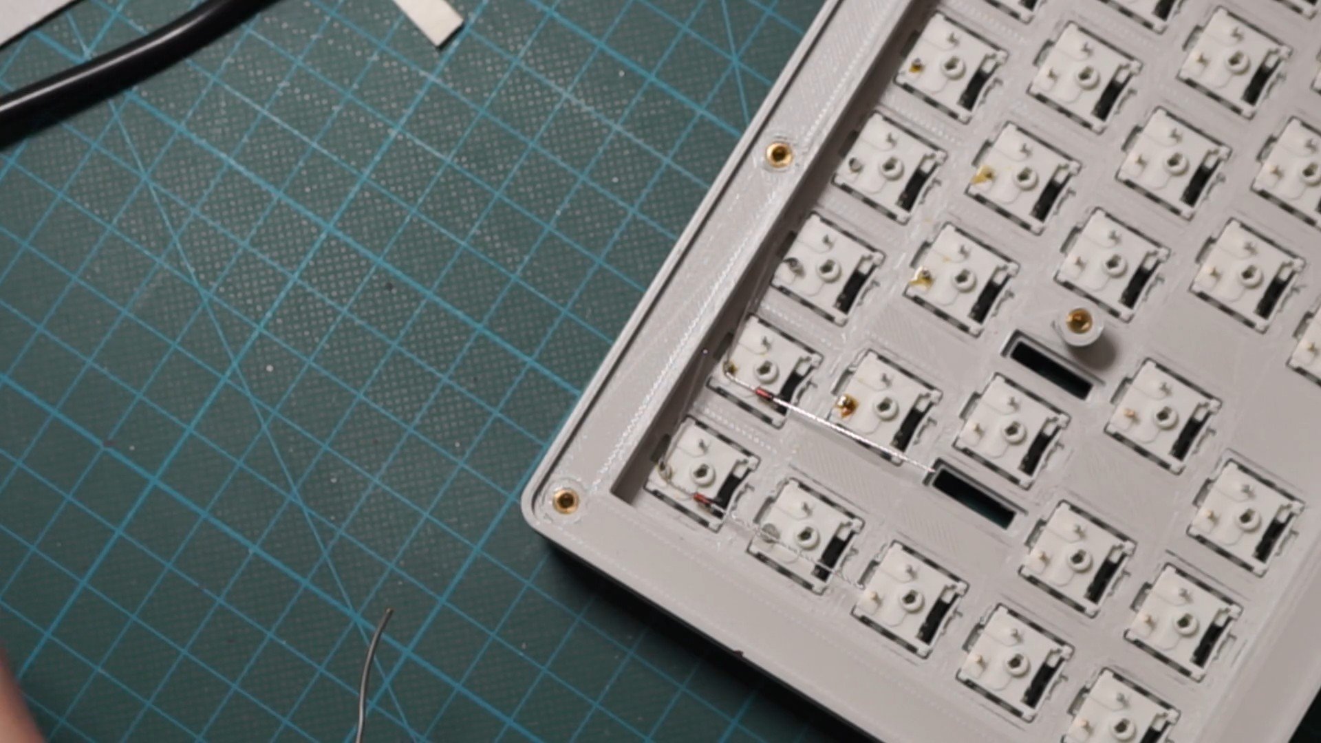
Now we solder the diode right on the bend to the left pin switch. Just heat up the small solder blob we previously put on the pin until it melts, move the diode next to it, remove the iron and wait until the tin cools down. Easy-peasy. Repeat for all switches on the top row. When you finished the row cut the excess wire on the anode (just near the solder point).
Time to connect all diodes together.
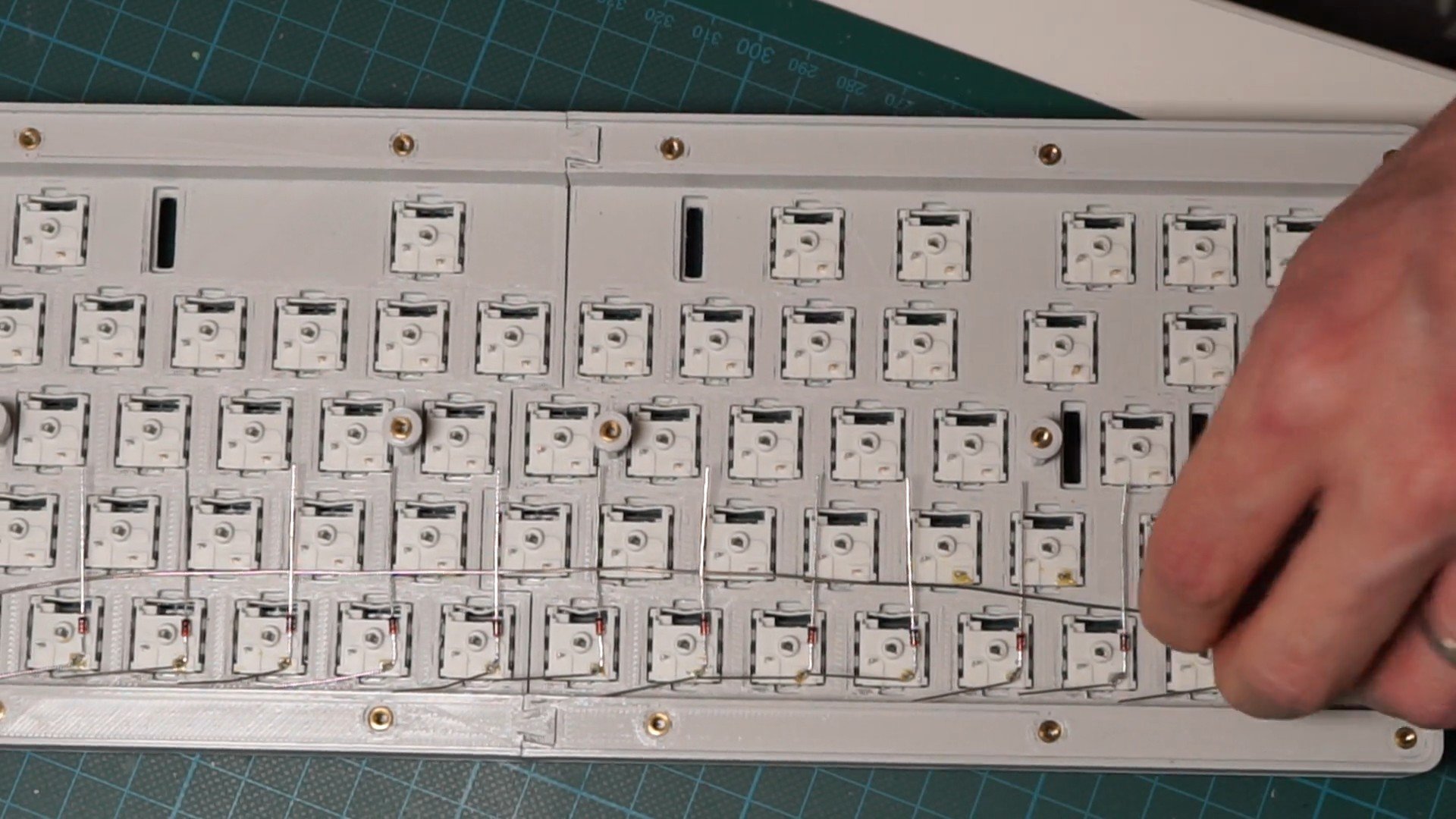
Thread one of the 5 wires we cut through the diode cathode pins (the one that is now facing down). Move the wire close to the bottom of the switches on the first row and start soldering all the cathodes together.
Repeat for all the rows.
Next we are going to insulate the rows with some tape. I used heat resistant tape because I had that at hand, but you can use whatever you want as long as it is electrically inert.
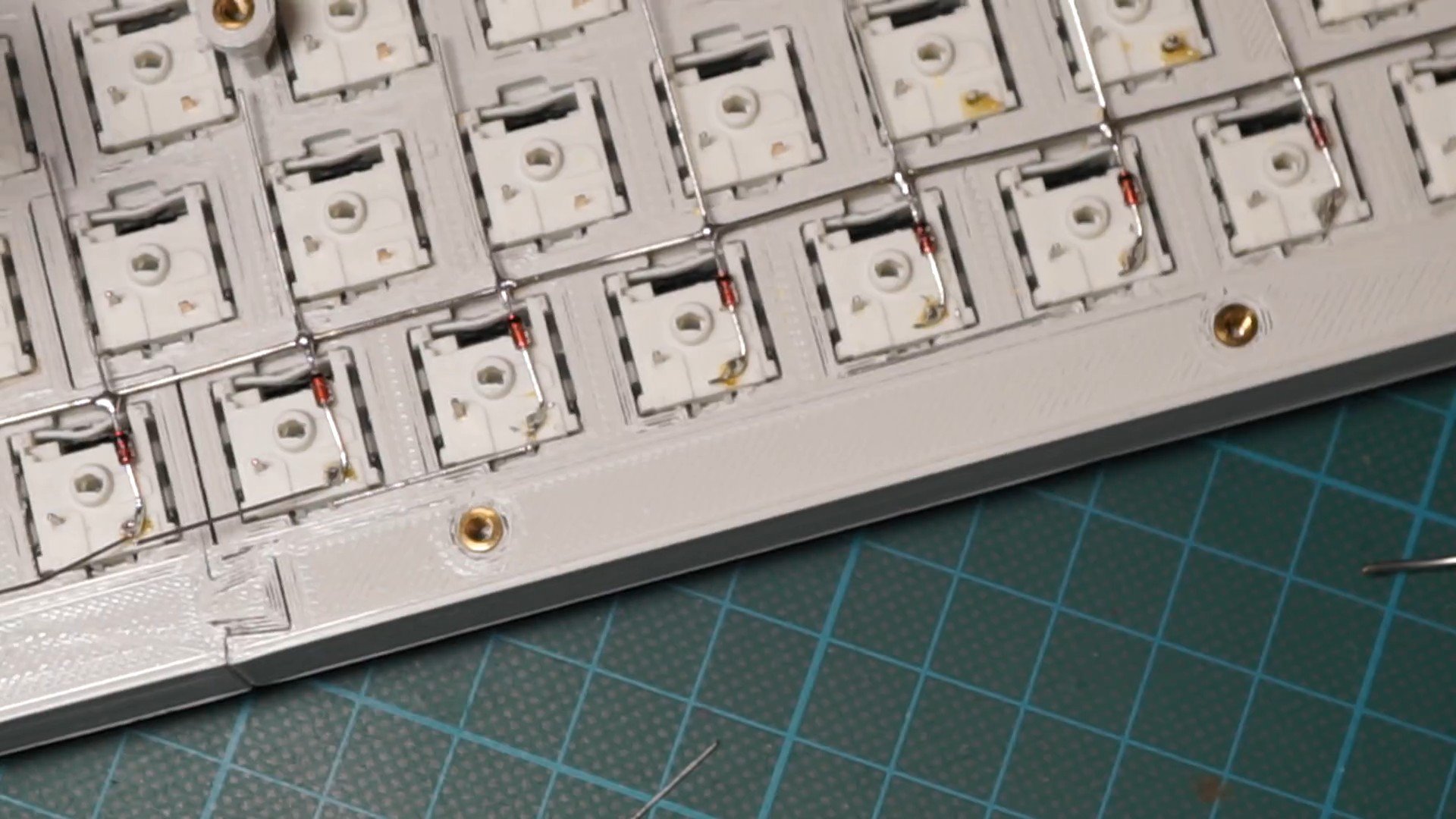
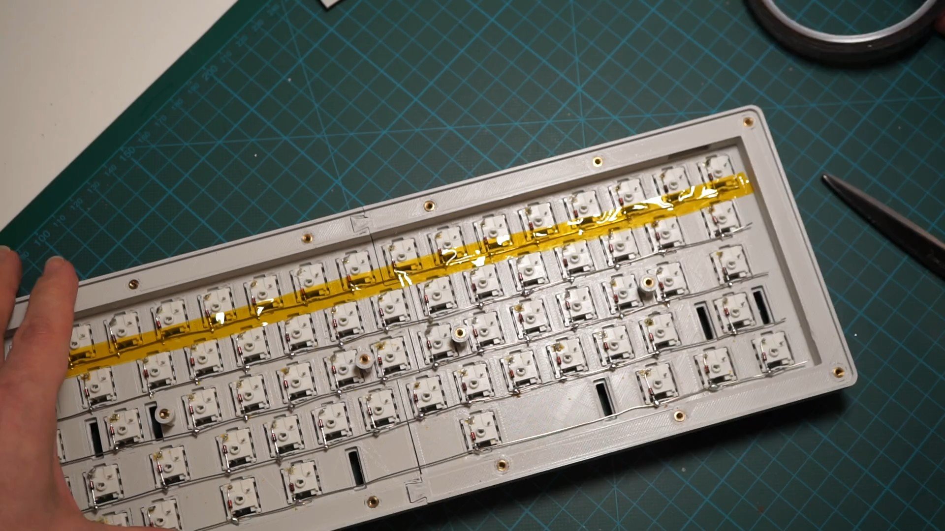
Time to connect those columns. The procedure is the same we did for the rows. Cut enough wires to cover all the columns. The length should be about 1.5 times the height of the keyboard. Peel the insulation and connect the right pins on the switches one column at the time. The switches won’t line up perfectly because of the keys staggering (unless you are building an ortholinear) so you get to be a little creative with your routing. At the end you can cut away the excess wires.
If you are designing a fairly standard layout, the bottom row will most likely have fewer keys compared to the others, so some of the columns will end up shorter but that’s totally fine.
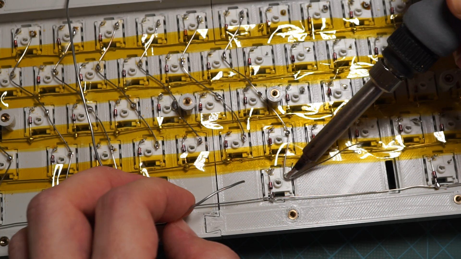
This is a good time to double check all your solder points. Make sure that all joints are secured and that you don’t have shorts between rows and columns. You can help yourself with a multimeter if you have one at hand.
And finally the controller! Take your ribbon cable and split it into 3 or 4 smaller chunks. I find it easier to work 4-5 wires at the time. These wires will go directly from the first switch of each column and the last on each row to the Teensy.
The keyboard I’m working on has 16 columns and 5 rows. So the following is the schema I’ll follow for my matrix. It’s better to write it down as I’m going to need it when compiling the firmware.

From the picture above you can see I’m using the blue pins for the rows and green for the columns. You can use whatever you want, there’s no rule, just avoid I/O marked with an X. Most of them are self explanatory (you can’t of course use ground or VCC), just be careful not to use pin 13 that is shared with the onboard LED. Many controllers have one I/O that pass through the LED and they tell me it’s not a good idea to use it for a keyboard matrix, so check that on your controller.
You made it!
At this point you should have something like this.
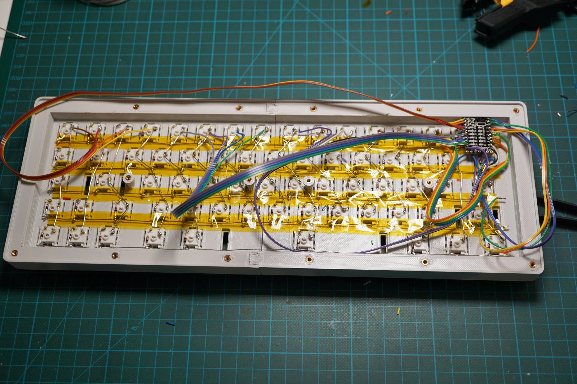
I like to keep my wires loose so it’s easier to work on the controller if I need to, honestly I wouldn’t recommend to cut cables too tight even thought they would look tidier. Whatever you choose, be sure to be able to access the reset button on the controller, we are going to need it the first time we burn the firmware, from that moment on we can initiate the “flash mode” with a key-combo.
All left to do is to flip over your keyboard, place keycaps and stabilizers and… code the firmware! But that is material for another tutorial.
