We’ve built our keyboard from scratch, now it’s time to put a brain into it.
A keyboard functionality may seem trivial but the firmware job is all but simple. Dealing with the USB HID interface is tedious, that’s why it’s good to start with a controller that has integrated keyboard/mouse/keypads support like the Teensy and some ready to use libraries.
There are various firmware we can choose from but for the sake of this tutorial I’m going to use QMK. It was born as a fork of Hasu’s TMK and developed into its own thing. Unfortunately at the time of this writing TMK doesn’t compile properly with Chibios (aka modern controllers like the Teensy 3.x) so we are going to work with its equally capable cousin.
The firmware I’m building in this article is for the keyboard we’ve hand wired in the previous chapter. Have a look at it if you haven’t already. Of course you can customize it to your needs.
The development environment
We are going to build the firmware from the source code so first of all we need to set up the development environment.
If you are on Linux, great we can be best friends, you are just a few packages away from compiling, Windows and Mac users need a little tinkering.
Windows
There are a few ways you can have this rolling. Probably the easiest is to install Debian or Ubuntu on a Virtual Machine like VirtualBox or dual boot and follow the instructions for Linux below. Alternatively you can try with MSYS2, the benefit is that you don’t have to install a VM and a whole operating system in it; the downside is that it’s a little bit more complicated and error prone to set up.
Technically you could also try with the Windows Subsystem for Linux if you have it already installed, but I wouldn’t suggest that. I had issues compiling various pieces of software with it; while I’m fairly certain you can make it work, I wouldn’t risk wasting time trying to figure out errors that are caused by the environment and not your code.
First of all install MSYS2, you probably need the x86_64 version. Set the installation folder to something easy and quick to access like C:\msys64.
Close any MSYS2 terminal you may have open and launch a new MSYS2 MinGW 64-bit terminal.
You’ll be presented with a command line tool. MSYS2 uses pacman as package manager. Packages are software and libraries you can install on your system. Before installing the tools we need to update the package database and the base system. Issue the following command:
pacman -Syu
It will ask for confirmation. Proceed and wait for the upgrade to complete. It may or may not ask you to close and reopen the terminal, do as it asks and issue the same command again. This will ensure a full system upgrade.
Close and reopen if asked and proceed with the installation of git:
pacman -S git
From here on the installation is more or less the same for all systems, skip the other OSs and proceed to the next section.
Mac
While the situation on Mac is slightly better, I still recommend to compile the firmware in a virtual machine (VirtualBox or whatever) with a linux in it. That keeps your system clean and doesn’t require you to install software you’ll probably rarely use. If you proceed this route, jump to the linux installation instructions.
If you want to go “native”, you need to install Homebrew and Git.
Linux
You are all set. Install Git and proceed.
Download QMK
We now use git to clone the QMK code locally, open the terminal if you haven’t it already and in your home directory issue:
git clone https://github.com/qmk/qmk_firmware
Move to the QMK directory:
cd qmk_firmware
Time to install all the packages required to build the AVR and ARM code.
util/qmk_install.sh
You may need to close the terminal window and reopen it, if so be sure to go back to the qmk_firmware directory.
Finally install some additional modules:
make git-submodule
At this point you should have a working environment. Let’s test it out to check that everything’s in place. Issue the following command:
make handwired/onekey/teensy_32:default
This should compile a test code made for the Teensy 3.2. If you receive some errors it could be for a gazillion reasons. You may try to check the QMK documentation.
Clean up the mess and prepare for the next stage:
make clean
Prepare the code
It’s time to customize the firmware for your keyboard. That is done by editing a few files with your favorite text editor. I baked for you a base structure you can use for your Teensy 3.x projects, most of the files are just general information about the controller capabilities, you can safely ignore them; what matters to you is the matrix definition and of course the keyboard layout.
So let’s start by downloading some base files.
Unzip the archive inside the keyboards folder. On windows/msys2 the full path will be C:\mysys64\home\[your-user-name]\qmk_firmware\keyboards, on Linux and Mac will be in the qmk_firmware folder inside your user’s home.
The archive contains a folder called 3dwf. The following is the directory structure:
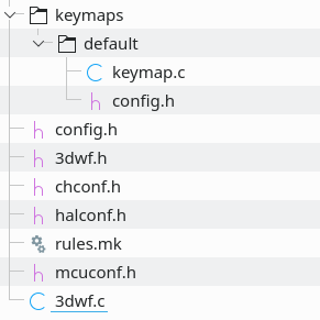
The files we need to change are only: rules.mk, config.h, 3dwf.h, keymap.c. We are going to analyze each of them, be sure to open the files in your text editor.
Controller definition: rules.mk
In rules.mk we are telling QMK what controller we use and what main features we need.
The first section is the most important. I’m using a Teensy 3.0, quite dated but that’s what I had around, so the MCU definition will look like this:
MCU_FAMILY = KINETIS
MCU_SERIES = K20x
MCU_LDSCRIPT = MK20DX128
MCU_STARTUP = k20x5
BOARD = PJRC_TEENSY_3
MCU = cortex-m4
ARMV = 7
The above tells all the firmware needs to know about my controller, if you have a different Teensy (eg: v3.2) just replace the values with those indicated inside the file.
At the end of the file you’ll find the build options. They are pretty self explanatory but I’d stick with the defaults for now. I activated NKRO of course and also the MOUSEKEY so I can emulate a mouse.
PIN definition: config.h
Here we are going to define the USB device descriptor (ie: how’s the keyboard identifies itself to the operating system) and the PINs we used on the controller.
You are rather free to change the descriptor in any way you want, but you can leave it as it is for now.
/* USB Device descriptor parameter */
#define VENDOR_ID 0xFEED
#define PRODUCT_ID 0x0000
#define DEVICE_VER 0x0001
#define MANUFACTURER Matt3o
#define PRODUCT 3dwf
#define DESCRIPTION A custom keyboard
What matters is the number of columns and rows we used in our matrix and the PIN ids.
#define MATRIX_ROWS 5
#define MATRIX_COLS 16
Our keyboard has 5 rows and 16 columns and those pins are defined by the following two constants:
#define MATRIX_ROW_PINS { D0, A12, A13, D4, D7 }
#define MATRIX_COL_PINS { C2, D2, D3, C3, C6, C4, C7, D1, C0, B0, B1, B3, C1, D6, D5, B2 }
The pins must be listed in the same order as you soldered them to the matrix. So D0 will be the first row, A12 the second and so on. C2 will be the first column, D2 the second, …
You can reference to the Teensy 3 and Teensy 3.2 diagrams to find the pin names. Have a look at the following extract:
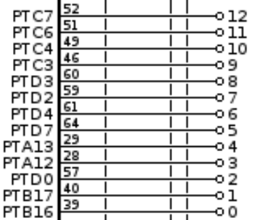
Pin labelled on the Teensy board as 0 goes by PTB16, so that will be our B16 (ignore PT). Pin 1 is B17, 2 is D0, 3 is A12. As you noticed the naming is pretty random so take extreme care when listing the pins.
By now you have probably wrote down your pin numbers. Do yourself a favor and double check them :) I know by personal experience that it’s very easy to get them wrong (either the name or the order).
Defining the matrix: 3dwf.h
This is a tricky one. 3dwf is the name of the 3d printed keyboard I made. If you wish to rename it you need to open the 3dwf.c file and update the reference to 3dwf.h you find inside, then you can change the main directory, the 3dwf.h and 3dwf.c file names. But let’s stick with the default for now.
3dwf.h is where we tell the firmware how we constructed our matrix.
#define LAYOUT( \
    K00, K01, K02, K03, K04, K05, K06, K07, K08, K09, K0A, K0B, K0C, K0D, K0E, K0F, \
    K10, K11, K12, K13, K14, K15, K16, K17, K18, K19, K1A, K1B, K1C,      K1E, K1F, \
    K20,      K22, K23, K24, K25, K26, K27, K28, K29, K2A, K2B, K2C, K2D,      K2F, \
    K30,           K33, K34, K35, K36, K37, K38, K39, K3A, K3B, K3C, K3D, K3E, K3F, \
    K40, K41,      K43,                K47,                K4B, K4C, K4D, K4E, K4F  \
) \
{ \
    { K00, K01,   K02,   K03, K04,   K05,   K06,   K07, K08,   K09,   K0A,   K0B, K0C, K0D,   K0E,   K0F }, \
    { K10, K11,   K12,   K13, K14,   K15,   K16,   K17, K18,   K19,   K1A,   K1B, K1C, KC_NO, K1E,   K1F }, \
    { K20, KC_NO, K22,   K23, K24,   K25,   K26,   K27, K28,   K29,   K2A,   K2B, K2C, K2D,   KC_NO, K2F }, \
    { K30, KC_NO, KC_NO, K33, K34,   K35,   K36,   K37, K38,   K39,   K3A,   K3B, K3C, K3D,   K3E,   K3F }, \
    { K40, K41,   KC_NO, K43, KC_NO, KC_NO, KC_NO, K47, KC_NO, KC_NO, KC_NO, K4B, K4C, K4D,   K4E,   K4F }  \
}
There are two sections. The first is the list of all our keys, the spacing is purely for ease of reading. The second block tells the firmware how the keys in the rows are actually connected… or not connected.
The naming of the keys is completely arbitrary but I believe this is a good way to represent the matrix. K00 means Key in Row 1 Column 1 (we start counting from zero). The first digit indicates the row and the second the column. All keys in the first row will be K0_, keys in the second will be K1_, in the third K2_, … All keys in the first column will be K_0, in the second K_1, and so on. This way if I tell you K3A you know that we are talking about the 11th key in the 4th row. Easy as 3.14.
In the following image you can see how the columns wires are connected to the switches.
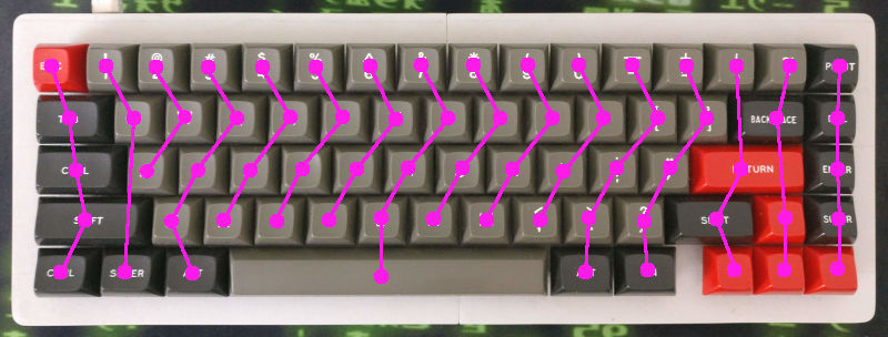
In the first row all keys are connected so we write down all the 16 keys, conveniently named from K00 to K0F. Let’s move on to the second row where we miss one key. There’s no switch between ]} and BACKSPACE. The 14th wire jumps from K0D (PIPE) to K2D (RETURN) and so we skip K1D altogether.
In the third row we miss two more keys. Looking at the picture the second wire goes from the Q (K11) key to the SUPER (K41) key jumping two rows. So the first key to skip is K21. The 15th wire goes from BACKSPACE (K1E) to the UP arrow (K3E), so the missing switch here is K2E. You got the gist by now.
The second block is divided into 5 groups each enclosed between { … }, those are of course the rows and all we have to do is replicate what we did before but this time instead of skipping the missing keys we put the KC_NO keyword in their place.
So the first block will contain a number of elements that is equal to the number of keys on your keyboard (in this case 68). The second group will have ROWS × COLUMNS elements instead (16 × 5 = 80).
Congratulations, the worst is behind us. Now to the fun part: keymap definition!
Keymap definition: keymap.c
This is where the action takes place, AKA where you actually define what switch does what.
First of all we enumerate the layers:
enum layer_names {
     _BASE,
     _FN1,
     _FN2
};
_BASE of course is the default one. _FN1 and _FN2 are two layers that are activated by pressing an FN key. They are usually momentarily layers (ie: activated as long as you press the FN key), but they can be toggle layers to –for example– activate a different keyboard layout like COLEMAK or DVORAK. Or of course you can have no layers at all, in which case you just remove _FN1 and _FN2 from the list.
Next the layer definition:
[_BASE] = LAYOUT(
    KC_ESC, KC_1,   KC_2,   KC_3,   KC_4,   KC_5,   KC_6,   KC_7,   KC_8,   KC_9,   KC_0,   KC_MINS,KC_EQL,  KC_BSLS,KC_GRV, KC_PSCR, \
    KC_TAB, KC_Q,   KC_W,   KC_E,   KC_R,   KC_T,   KC_Y,   KC_U,   KC_I,   KC_O,   KC_P,   KC_LBRC,KC_RBRC,         KC_BSPC,KC_DEL,  \
    MO(_FN1),       KC_A,   KC_S,   KC_D,   KC_F,   KC_G,   KC_H,   KC_J,   KC_K,   KC_L,   KC_SCLN,KC_QUOT, KC_ENT,         KC_PGUP, \
    KC_LSFT,                KC_Z,   KC_X,   KC_C,   KC_V,   KC_B,   KC_N,   KC_M,   KC_COMM,KC_DOT, KC_SLSH, KC_RSFT,KC_UP,  KC_PGDN, \
    KC_LCTL,KC_LGUI,        KC_LALT,                        KC_SPC,                         KC_RALT,MO(_FN2),KC_LEFT,KC_DOWN,KC_RGHT
),
The structure follows the LAYOUT we previously defined in the 3dwf.h file, but this time instead of numbers we tell the firmware what we want the keyboard to output.
The list of all available keycodes can be found on QMK website. The only thing to note is that I’m using two momentarily function layers. they are defined as MO(_FN1) and MO(_FN2). The other most useful layer switching options are TG(x) which toggles the x layer, and OSL(x) that activates layer x just for the next key you press (so you tap the function key and the layer will stay active for just one key). There are other options and they are all listed in the official documentation.
[_FN1] = LAYOUT(
    KC_MUTE,KC_F1,  KC_F2,  KC_F3,  KC_F4,  KC_F5,  KC_F6,  KC_F7,  KC_F8,  KC_F9,  KC_F10, KC_F11, KC_F12, _______,_______,_______, \
    _______,_______,_______,_______,_______,_______,_______,_______,_______,_______,_______,_______,_______,        KC_DEL, KC_INS,  \
    _______,        _______,_______,_______,_______,_______,_______,_______,_______,_______,_______,_______,_______,        KC_VOLU, \
    _______,                _______,_______,_______,_______,_______,_______,_______,_______,_______,_______,_______,_______,KC_VOLD, \
    _______,_______,        _______,                        _______,                        _______,_______,KC_HOME,KC_PGDN,KC_END
),
Next I’m defining the first layer. Nothing fancy here. The only thing to note is that I’m using _______ (7 underscores) to identify transparent keys. Those are the keys that are cloned from the base layer.
To spice it up a little I also added a third layer. We activated the mouse compatibility earlier, so I’m making good use of it and added mouse movement to the arrow cluster, for when you are so tired you can’t even bother moving your hand out of the keyboard.
Compile and flash!
Time to compile, baby.
make 3dwf
If you get errors the most likely mistake you made is in the layout definition in the 3dwf.h file. Double check you wrote down the right number of keys. Also check that your MATRIX_ROWS and MATRIX_COLS are correct. Finally review your layer layouts, you may have missed a key or two.
If all goes well you should end up with a set of files in the ./build directory. We are using the Teensy loader to upload the firmware so the file we are going to flash is 3dwf_default.hex.
Download and install the Teensy loader for your operating system (Linux users can install the command line tool that is likely available on your distro repositories).
Connect the USB cable. Pick the 3dwf_default.hex file. Press the Teensy reset button. Pray your god. Flash it!
If you are using the command line tool you can issue the following:
teensy_loader_cli -mmcu=mk20dx128 -v -w 3dwf_default.hex
mmcu value varies based on the Teensy version you have. You can list the compatible boards with teensy_loader_cli --list-mcus.
If the keyboard is not responding, try to disconnect and reconnect the USB cable.
Congrats! You made it!
Note that the QMK has a lot of helpers, configurators and online tools to make the compilation and flashing of the firmware easier. I kinda went for the hard route here, but I believe it’s important to understand how the code is structured.
Troubleshooting
All keys are working but one
Check the solder points for the offending switch. Resolder it even if it looks fine. If that doesn’t work you may need to change the switch, it’s very rare but they can be faulty. Also check the diode orientation.
One column of keys doesn’t work
Check that you defined the right column pin in the config.h file. If that is correct check the solder job on all the switches on that column and on the wire that goes from the controller to the column. Also check the diodes orientation.
Two or more columns are swapped
You very likely defined the pins order wrongly in the config.h file.
No key is working
Calm down. Take a deep breath. You probably defined the wrong controller parameters in the rules.mk file. Also check diodes orientation.
OMG! Everything’s working as expected!
I KNOW! Unbelievable.
Closing words
This concludes our first adventure in custom keyboard building. The journey is far from over, though. There’s more that needs to be covered, first of all designing a PCB, because hand-wiring is fun and all but a PCB really makes your project look cool.
I would also like to add some step-by-step tutorials on customizing existing keyboards, retrofitting old keyboards cases, restoring vintage equipment. There’s still a lot to cover, so stay tuned and please share if you liked this tutorial.
Happy making! And let me know if you build any keyboard following my tutorials.
Comments
This is awesome
Finally! An good guide on how to build a handwired keyboard!
No soy de habla inglesa pero usted es un hombre ejemplar, muchas gracias por este material de apoyo, espero que la vida le devuelva las cosas buenas que haces. Saludos desde República Dominicana.
arch btw ( ͡° ͜ʖ ͡°)
is there anything else?
A question occurred to me, in my case I will create one of 87 keys, what would the matrix distribution look like?
It’s hard to say, depends how you route the wires. You surely need one additional row. As per naming standard you could use K000, K001, K002, … in the 3dwf.h
With a teensy 3.2, can I do it?
YES! Check the files, you’ll find instructions to use a teensy3.2
Great tutorial, thank you so much for the effort.
Couple of questions:
1. There is no reason this wouldn’t work with regular spst momentary switches right, so long as they are wired into a matrix and mapped correctly to the firmware?
2. Can I map a momentary switch to toggle an on/off action. Ie push a button toggle until I push again to deactivate ? Like a caps lock but with other keys. Does that need it’s own layer or can I attach osl(x) or something like it permanently to a specific key?
3. Is there a way to map analog potentiometers (think a shuttle control or volume control)
My hope is to construct a custom box to control Adobe video editing software. I also have a friend who is building a really crazy flight simulator, this seems like a really good way to make cockpit panels.
Sorry for all the questions, I am really excited to start a project with this.
1. yes, they totally work
2. yes, that is possible with a toggle function layer, you don’t need a special layer for that, you can use a previously defined layer
3. I haven’t done that myself but I believe it is possible, easier to use rotary buttons (similar to a mouse wheel)
Ciao Matt3o,
Your previous guide on how to attack kb firmware was a great source of inspiration, but after struggling with my Teensy 3.2 I gave up.
Now with this new guide, more in depth and with the files to work with Teensy 3.x I think I am compelled give it another try! Here are a couple of questions though:
– In order to use your firmware on a Teensy 3.2 one needs to change the parameters in rules.mk to those of the 3.2, but are there any other definitions that need to be changed in the rest of the files?
– I would like to go big and make a 105 ISO kb (the Teensy 3.2 has 34 digital pins, so there should be no problem in that sense). For the extra columns I guess K0H is not an option, so should I go for something like K000 … K021?
Thanks a lot!
– no, everything should be in rules.mk
– K000, K001, …, K022 is totally viable
Can I use a STM32F103C8T6 (STM32F103) as a MCU? I see it mentioned in the qmk compatible microcontroller github page, but I can’t find any handwired guide related to it. If you can please let me know how different the process would be compared to a teensy.
it is supported by chibios it’s just a matter of finding the right config. Check if there’s any chibios based project using it
Hey there Matt3o,
wanted to share that i learnt quite a bit from your guide here, and i published one too. linked your guide, within here: https://hackaday.io/project/173766-qmk-powered-laptop-keyboard as well as Frank Adam’s instructable.
Hope you like it too.
really a matter of gymnastics.
thanks for the heads up!
Change LAYOUT to KEYMAP define in your keymap.c file and everything is fine. Excellent doc
Can I use a teensy 2 for this?
absolutely! but you can’t use the files I baked for this tutorial
Can you provide some info or link to a good site that would tell me what files I would need to get this to work with a teensy 2? Your guide is invaluable but unfortunately I used a teensy 2 in my build and I am stuck at the firmware.
Teensy2 is super easy to configure, you don’t even need chibios. Check the directory keyboards/handwired/onekey/teensy_2/
Dovrò aspettare un anno per il prossimo articolo?
Hey! I’ve got a custom board I’m working on here, it has an ATMega32u4. What would I put under rules.mk for it to be compatible?
it’s a completely different controller. The easiest is to check in the examples one keyboard that already uses the ATMega32u4. Join deskthority or the discord channel if you need further help
Might be helpful to someone.. I couldn’t find the .hex file after I compiled it, it left me with a .bin file I could see. Looking back at the logs, the .hex file was left in the .build folder and I just needed to copy it from there.
thanks for the headsup
Amazing
I am thinking to try to flash qmk to gk61x. Will I be able to do something like this for that if I can figure out matrix of gk61x even though it is 3rd party?
I’m not familiar with that keyboard, but if the firmware is flashable and the controller is supported by GMK/TMK you can certainly do it
Thanks.
I appreciate your work. I never planned to learn how a keyboard works.
Matt3o
Thanks for this great tutorial, I have successfully built a custom keyboard with a Teensy 3.2 using this as a guide and am working on another with a Teensy LC.
I’m not able to get it to compile with the Teensy LC though for the life of me. To test, I downloaded your 3dwf files as-is and only changed rules.mk to the settings listed for Teensy LC and that also failed.
Any ideas?
Compiling: keyboards/3dwf/3dwf.c In file included from quantum/quantum.h:24:0,
from keyboards/3dwf/3dwf.h:19,
from keyboards/3dwf/3dwf.c:17:
./lib/chibios/os/hal/include/hal.h:118:21: fatal error: hal_lld.h: No such file or directory
^
compilation terminated.
[ERRORS]
|
|
|
tmk_core/rules.mk:383: recipe for target ‘.build/obj_3dwf_default/keyboards/3dwf/3dwf.o’ failed
make[1]: *** [.build/obj_3dwf_default/keyboards/3dwf/3dwf.o] Error 1
Make finished with errors
Makefile:563: recipe for target ‘3dwf’ failed
make: *** [3dwf] Error 1
I have tried with both QMK 0.10.22 and 0.10.49 with the same results.
Any idea what I am missing?
-Jeff
I figured it out… some of the other files like mcuconf.h, halconf.h and chconf.h were older I think and needed to be replaced. I got them from the handwired/onekey/teensy_lc and then I was able to compile it for Teensy LC.
-Jeff
Hi there,
Thanks for you’re comment, i’m trying to compile it with a Teensy LC and I have exactly the same error messages as you.
I replaced the files in the 3dwf folder you suggested (mcuconf.h, halconf.h and chconf.h), but unfortunately I’m still getting the same error messages.
Did you change anything additionally?
If you have problems installing qmk (util/XX_install.sh), use util/qmk_install.sh instead
This is awesome. Thank you for posting.
I’m building my first keyboard, and haven’t been able to find a guide to make a fully custom layout
Additional help for Teensy LC: since I couldn’t compile using an Teensy LC I had to change some files.
In “rules.mk” I added “USE_CHIBIOS_CONTRIB = yes”
For “mcuconf.h” I had to replace it with the file from handwired/onekey/teensy_lc
This one was of great help
In May 2021 the qmk firmware was updated and archive on the directory util/msys2_install.sh change and now are in util/install/msys2.sh
thanks for the heads up!
Sorry, comments are closed but you can still get in touch with the contact form.