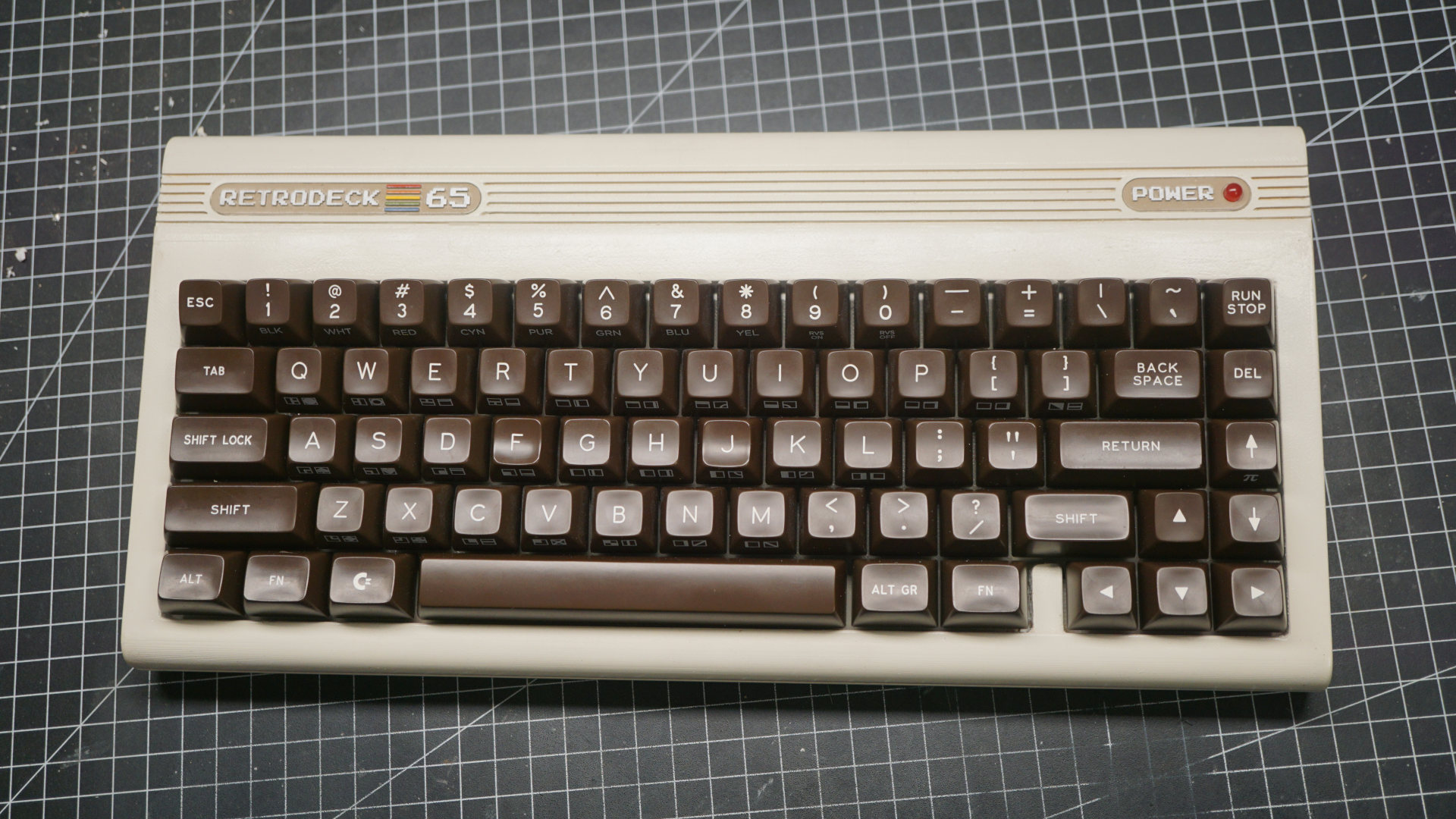
Few years ago we run the wonderful SA Retro keycap set, it was quite a small group buy but a few vintage computing addicts were able to grab what it is now a very unique and rare set. I used the keycaps on a 60% keyboards for a long time but I knew they deserved a better home so I designed a Commodore 64 case I could easily 3D print.
When I don’t know exactly how the keyboard is going to look I like to work with OnShape as it’s a very fast and easy parametric CAD to prototype with. The case design is overall very simple, the challenge is to try to cut the model in a way that doesn’t require supports when printing with a filament 3D printer. Supports are a waste of printing time and material and I try to avoid them as much as possible.
To do that I had to cut the top in two pieces. My plan was to sand, putty, prime and paint the case anyway so splitting wasn’t a problem for me, but I’m offering you the original model (from OnShape… very messy) or you can download the STEP files from the link at the bottom of this post, so it should be rather trivial to adapt the design to your needs.
Please note that I have a big 3D printer (400mm³) and I can fit the whole keyboard horizontally, if you have a standard 250×250 printer things get a little more complicated but I’m offering a pre-cut (albeit untested) version too.
Let’s start from my build video and if you are interested in moving forward I’ve added some technical details down below.
A quick BOM.
- 3D printed case (duh)
- The paint I used is Pearl White RAL1013
- Any solder-in 65% PCB with split backspace support, the plate has no support from the case so you really want to solder those switches. I used Polarity Works BT65 that also supports bluetooth.
- PCB mounted stabilizers. I used white Gateron Screw-in Stabilizer V2 just because they match Pearl White, but any make/brand works, they are not visible anyway
- If you want to go wireless I’d suggest to get a bigger battery for better autonomy
- 1x 5mm red LED for the power indicator with a 150ohm resistor
- Short and flexible USB-C extension cable
- 68 switches (make it 70), I used Zeal Clickiez (the light ones)
- 8×M2.5 threaded inserts and 10mm long M2.5 screws
- 6 Rubber feet
As filament goes I’d suggest ABS+ or Tough PLA (like GreentecPro) if you plan on sanding. Pure PLA has a very low vicat softening point so sanding becomes tedious and you have to go very slow.
The switch holes are exactly 14×14mm, meaning that elephant foot will make them quite a tight fit. You may try to compensate it on your slicer or you’ll probably need to file the holes just a tiny bit.
To merge the main plate to the “hat” I used epoxy glue, but that was a mistake. The glue is very fast curing and generates a lot of heat very quickly, that bent the plastic and the seam was not perfect. Nothing that can’t be fixed with some putty but still probably contact glue would have been better.
I used many layers of an automotive filler primer and long sanding sessions to make the 3d printed case look half decent. To fill the bigger seams I’d use epoxy putty, there are many kinds, the one used to repair car bumpers is slightly flexible and I’d suggest that (body filler for plastic, it’s generally black/dark brown). In the video I used the gray one that is better for hard surfaces and metal.
The case doesn’t hold the PCB in any way so I’m afraid it has to be solder-in switches. Even though it might work with hot-swap (if you can find one that fits) still I’m not sure the grip would be strong enough. The Polarity Works PCB I’ve used works pretty well and it has all the features I needed. It has also bluetooth and can be easily configured with the online configurator.
Regarding bluetooth I’d advise to get a beefy battery. The PCB comes with a 1200mA one but the case is big enough and I was able to fit a 3700mA. I still don’t know how much it lasts, but I’m guessing 6-8 weeks (update: it turned out to be actually 4 months on a single charge).
The back of the case of course is not flush with the PCB, that means that the USB port has to be routed somehow. I used a small flexible extension cable which is press fit into the case. Unfortunately the USB port on my PCB is a bit temperamental so my suggestion is to solder the extension directly onto the PCB (Polarity Works supports a solder-in USB extension).
I designed the USB port hole exactly for my cable so your mileage may vary depending on the kind of extension you use, I’m sorry I can’t offer a one-size-fit-all solution here. Hopefully with the STEP files you’ll be able to customize the case to your needs.
I used white Gateron stabilizers just for the look but I’m not a big fan of them. It took me quite some time tuning and lubing them to make them work. They are made of a soft plastic that is very tight on the wire. You have to loosen the grip and add a good amount of lubricant; if you are up for the task they are okay but I guess there are easier to install stabs around (Durock are expensive but hassle free).
The power LED was very simple to connect as my PCB supports pass-through LEDs for backlighting. All I had to do was to connect the LED to the backlight leads of one of the switches. The square pad is generally ground. Remember to check your LED specs, mine was very low voltage and I had to add a 150ohm resistor otherwise it would burn.
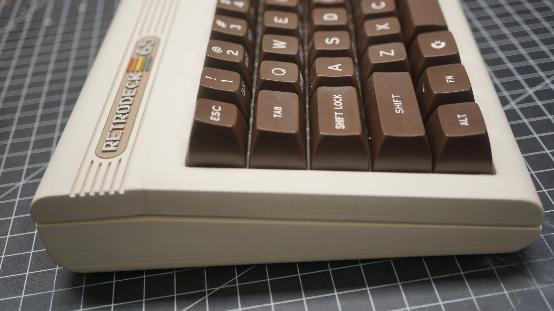
I printed the Retrodeck and Power badges with a resin printer (flush on the plate) and hand painted them with acrylics. I’ve also added a couple of layers of glossy varnish to make them more authentic and to have the chrome paint pop. The result is decent but I’d recommend to print a couple of each, experiment and pick the best looking one.
Overall I made quite a few mistakes but at the end it came out really nice and I’m very happy with it. The putty cracked in a couple of places, but I was able to fix it later applying a better putty and painting over again.
One last note about the switches. I installed Zeal Clickiez because it’s all people talk about these days, but they are less exciting than I expected. They are fine, sturdy switches with a retro feeling close to that of Alps’. I don’t regret buying them as this is not my main keyboard, but I would not put them on my daily driver. They are very hard at the very top but once passed the activation point they are very light causing a strong bottom down. Maybe it might help adding soft o-rings, if you are into those sort of things. Now I kinda want to build an Alps switch board, though.
Please let me know if you use any of the files I posted below and don’t forget to send me a link to your builds!
Download the 3D files!
Comments
SA Retro R2 when?
I’m trying!
oh please… I sacrifice a lamb for you!
Hi, I’m new to this and looking to build a C64 inspired keyboard too. Where would an Sa Retro R2 be announced? Thanks.
I’m trying to get SA Retro or MT3 Retro done. Stay tuned! Check this blog or my discord https://discord.gg/xBVuZnjDM2.
You my sir, have been sent from the heavens
Really impressed by this and would love to build one myself.. but I am shocked at the price of having this pieces printed at a 3D print shop. The group-buys for similar boards don’t seem so ludicrous now.
Considering getting myself a 3D printer just to make this beautiful piece of keyboard art.
totally worth it! :)
Sorry, comments are closed but you can still get in touch with the contact form.